


Bit depth, PWM and frequency
I have briefly shown how to resample a digital audio recording to play it out at a different pitch (i.e. at a different frequency).
Using PWM (pulse-width modulation) as a form of DAC (digital to analog converter) introduces some additional constraints we must be aware of when designing a player.
As we have seen, inside a microcontroller (such as the ATmega328P used in the Arduino Uno) a PWM is typically implemented in hardware using a timer that counts up from zero to a maximum value (e.g. 255) and a comparator that checks when it is time to turn the output off.
If we use an 8-bit counter for the PWM and let it count to the maximum, it has 28 = 256 possible values. With an 8-bit counter we will not be able to use more then 8 bits for each audio sample, that is 8 bits of audio bit depth (resolution), but that was expected.
PWM resolution, timer clock and playing rate
It may be less obvious that the PWM resolution also sets a limit on the playing rate, i.e. the frequency we are using to play out the audio sampled values.
That happens because counting from zero to the maximum value (e.g. 255 for an 8-bit timer) takes time. An 8-bit timer requires 256 input (clock) pulses for a full count:
Playing_rate = timer_clock / 256
The timer clock frequency is usually selectable. In the case of the ATmega328P (Arduino Uno) the highest possible value is the same as the CPU clock: 16 MHz.
So the maximum playing rate for an 8-bit PWM DAC is:
Playing_rate = 16000000 Hz / 256 = 62500 Hz
62.5 kHz are plenty enough for audio, even considering that, to prevent undesired audible artifacts, the playing rate should be at least double the highest audio frequency we intend to play (I am skipping many subtle points here, especially because we are dealing with digitized audio, but this is the most important requirement).
So, no problems? Not so fast.
The cost of code
Getting the next sampled value from the original digitized wave and writing it into the PWM counter takes time, especially considering that a resampling is needed to output the desired audio frequency.
From a sample to the next, assuming the above 62.5 kHz, there are 256 CPU clock cycles available; they should be more than enough to do the necessary computations an other operations.
But…
…did I mention that I wanted to play six independent voices? The number of clock cycles available for each voice becomes:
256 clock cycles / 6 = 42 clock cycles
That is not easy to achieve using “casual C”. It requires a fair bit of optimization, including looking at the code produced by the compiler to see where precious CPU cycles could be saved.
Oh, I forgot: there is also the music score to read for each voice, the note duration to control, possibly also the note volume!
Forget the 256 cycles. A more realistic objective could be to do it all in 512 cycles. In that case:
Playing_rate = 16000000 Hz / 512 = 31250 Hz
31.25 kHz is still good. In fact, it took many iterations and a lot of work to get there, as I will show in the following posts.
From Audacity to 8-bit data
Before (finally!) talking about actual code, recall that my sampled guitar string had to be saved as 8 bits per sample to fit into the available microcontroller Flash memory.
This can be done in Audacity choosing File -> Export Audio… and selecting Other uncompressed files:
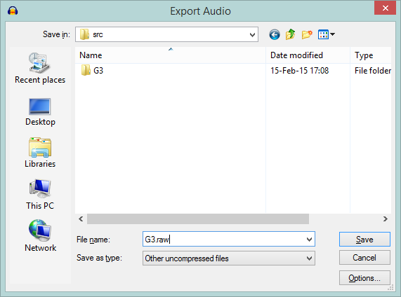
then pressing the Options… button and selecting RAW and Signed 8 bit PCM:
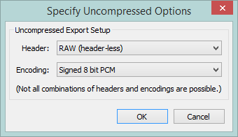
“RAW” means to save just the audio samples, devoid on any extra information such as the header that in the common audio formats (e.g. .wav) contains information about the samples.
“Signed” means that the value of each sample will go from -128 to +127, not from 0 to 255. The zero value will correspond to the central line (silence); applying volume and summing waves together will be easier and faster.
That’s all for the theory (at least for now…). In the next post: some code from my first ‘real’ player.