


How a PWM DAC works
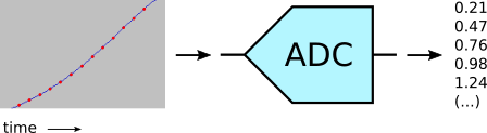
We have seen that a sound is digitized using a microphone to transform it into an electric signal, then by reading the istantaneous voltage of that signal at regular intervals with an Analog to Digital Converter (ADC), getting a series of numeric values.
The red dots in the image below mark the measurement time (horizontal) and the measured value (vertical).
To reproduce the sound from the recorded numbers, we do the exact opposite: we feed the same values at regular intervals to a Digital to Analog Converter (DAC)
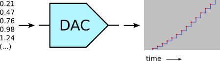
Note that the output voltage, once set, remains constant (horizontal segment) until the next value is converted, producing a staircase-like signal.
The signal will then be smoothed out using an analog “low-pass filter”, but that is not our main concern at the moment.
What worries us (what? You are not worried? You should be!) is that computers can do this because they have both an ADC and a DAC in their audio interface, but the Arduino Uno microcontroller only has an ADC.
But we have to produce an analog audio signal, because our ears are not digital. We need a DAC.
OK, but what is a DAC exactly?
The vertical axis on the above diagrams represents the voltage of the signal, so to recreate the original ‘dots’ we need to produce a precise voltage at regular intervals.
A DAC is exactly that: something that, given a numeric value, produces a voltage proportional to that number.
A hypotetical example:
value     voltage

0.21  ->  0.21 V (volt)

0.47  ->  0.47 V

0.76  ->  0.47 V
If we play out our sequence of numbers at the same frequency used to digitize the sound, i.e. the sampling frequency, the resulting sequence of voltages (filtered to make it smooth) will reproduce the original audio signal.
Cooking dinner with PWM
The ATmega 328P microcontroller used in the Arduino Uno has no DAC, but its hardware can do Pulse-Width Modulation (PWM).
What is PWM? I will cook up an example using my microwave oven; here is its panel:
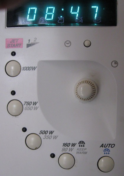
As you can see, it offers different power settings, from 90 W to 1000 W. However, the magnetron tube that makes the microwaves can only produce either 1000 W or nothing.
(I am sure of that: I disassembled and fixed my oven more than once. Last time I replaced a broken spring using a piece of underwear elastic band — but I digress)
If it’s either 1000 W or nothing, how can it produce, say, 500 W?
It uses a simple trick: it turns the magnetron on and off at regular intervals.

The orizontal axis shows time in seconds. It turns on the 1000 W magnetron for six seconds, then turns it off for another six seconds, then repeats this cycle until the cooking time has expired.
It generates 500 W on average by producing 1000 W half of the time (50%).
If I select a power of 750 W, it does this instead:
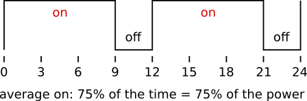
This time the heater, I mean the magnetron, is switched on 75% of the time.
This is PWM: it works by changing the pulse width (the ‘on’ time) within a constant-time cycle, 12 seconds in the case of my oven.
Just for information: the percentage of time the output (the magnetron) stays ‘on’ is called duty cycle. So with a 50% duty cycle I get 500 W, with 75% I get 750 W and with 100% (always on) I obviously get the full 1000 W.
PWM on the Arduino
To cook, er, to generate a variable voltage we can use one of the Arduino PWMs. In the simplest case, they work as 8-bit PWMs.
A basic 8-bit PWM is made with a counter that counts up from 0 to 255. At 0 it turns on a digital output, producing 5 V (volt).
We set a ‘comparator‘ value; when the counter reaches this value, it turns off the output (to 0 V) until the end of the cycle.
When the counter passes 255, it resets to 0 and automatically starts a new cycle, so a full cycle has 256 steps. The horizontal axis here shows the counter value:
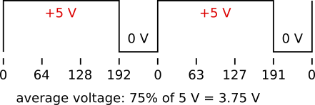
Looks similar to the microwave image above? Of course: it’s exactly the same PWM thing!
We can control the average output voltage by setting the comparator value:
value  voltage

000 -> 5 V * 1/256   = 0.004 V

127 -> 5 V * 128/256 = 2.5 V

191 -> 5 V * 192/256 = 3.75 V

255 -> 5 V * 256/256 = 5 V
(a technical note: for some of the AVR (Arduino Uno) timer modes we have to write 1 less than the desired value; in any case it would not be possible to use all values between 0 and 256, because those would be 257 values and the counter has a 256-step cycle. In this case we cannot output 0 V; fortunately we can mostly ignore this detail for an audio application)
The exact values are not important here; what counts is that the average output voltage is proportional to the time the output stays on, so the average of the output is our desired voltage: the PWM works as a DAC.
This is done by the hardware: we only have to set the desired output (average) value.
However…
Uh oh, there is some fine print at the bottom of the PWM contract:
- Catch 1: we must average the digital PWM output using an analog filter.
- Catch 2: even after filtering, the PWM cycle frequency could be heard as an audio signal. To prevent this, it should be out of hearing range.
- Catch 3: unwanted sounds (intermodulation products) are generated by the interaction between the PWM frequency and the audio signal. Let’s ignore this for now.
Is that all? Oh no, but that’s all for this post.
Next: squeezing our audio samples into Arduino Flash memory.